曾经在Arduino上为四段数码管写过驱动,所以对它还是比较熟悉的
首先拿一位数码管练练手!
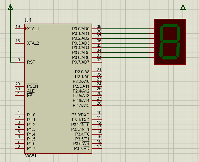
选择共阳极的七段数码管,接线如图所示:
这个测试最痛苦的点就是编写0——9十个数字的字模!!!
上图中从上到下连线依次为 a, b, c, d, e, f, g;
下图为个字母在数码管中的位置:
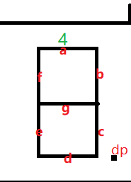
接下来就是手动计算字模了!
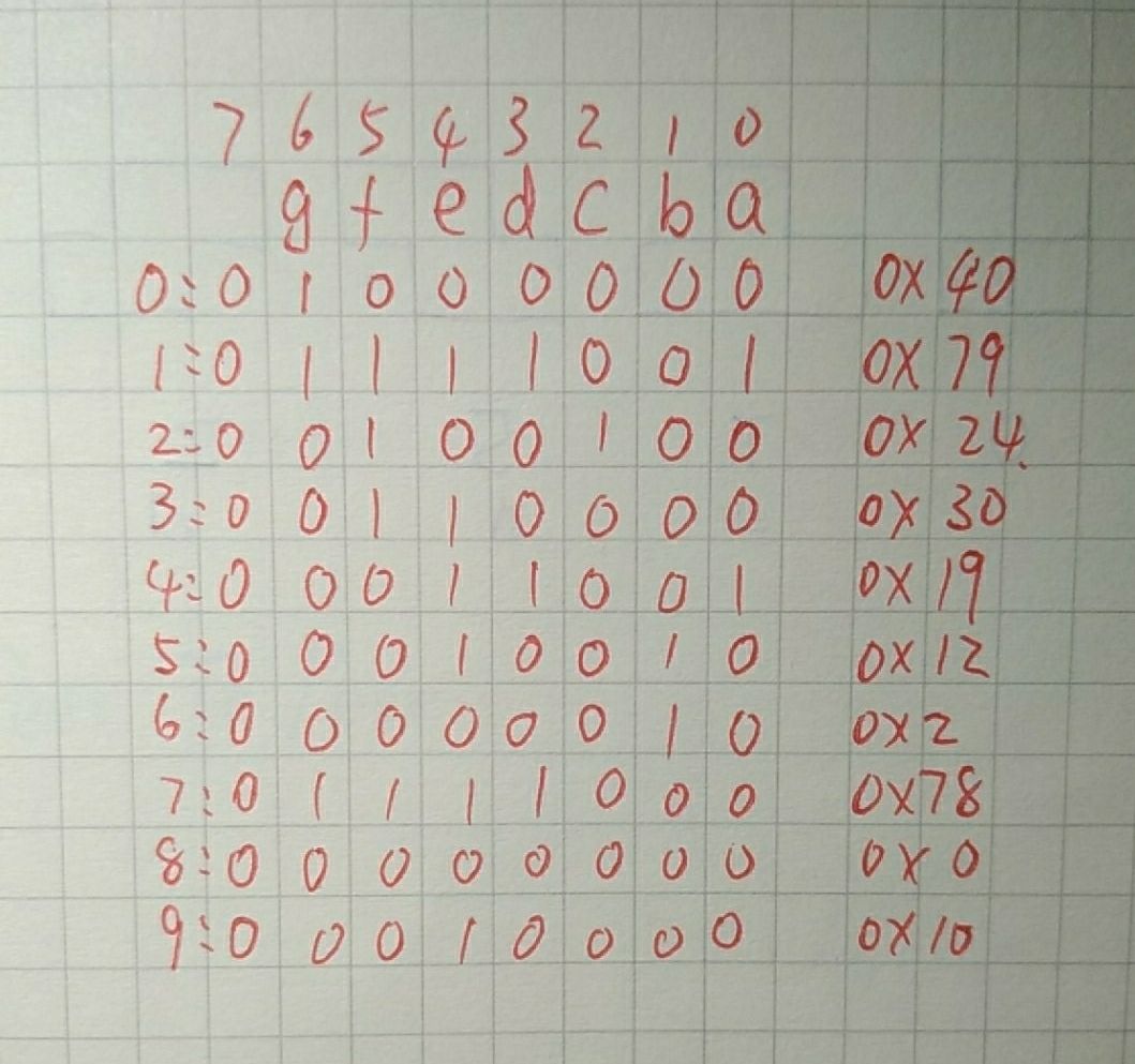
搞定!
有了字模程序就非常好写了!
/* Main.c file generated by New Project wizard
 *
 * Created:   周四 2月 28 2019
 * Processor: 80C51
 * Compiler:  Keil for 8051
 */

#include <reg51.h>
typedef unsigned char      uint8_t;

void sleep(int i)
{
    while(i--);
}
// 0~9 数字字模
const uint8_t n[10] = {0x40, 0x79, 0x24, 0x30, 0x19, 0x12, 0x2, 0x78, 0x0, 0x10};

void main(void)
 {
   // Write your code here
   uint8_t i;
   while (1)
   {

        for(i = 0; i < 10; i++)
        {
            P0 = n[i];
            sleep(65535);
        }
   }
 }
效果图如下:
那么六个这样的数码管如何在一起工作呢?
首先介绍一下 74LS245 (主要担心实物操作时单片机承受不住)
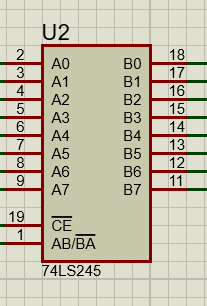
74LS245还具有双向三态功能,既可以输出,也可以输入数据。
当8051单片机的P0口总线负载达到或超过P0最大负载能力时,必须接入74LS245等总线驱动器。
片选端/CE低电平有效,当AB/BA=0时,信号由 B 向 A 传输;(接收)
还有 74LS04(就是反相器)(待会片选电路使用)
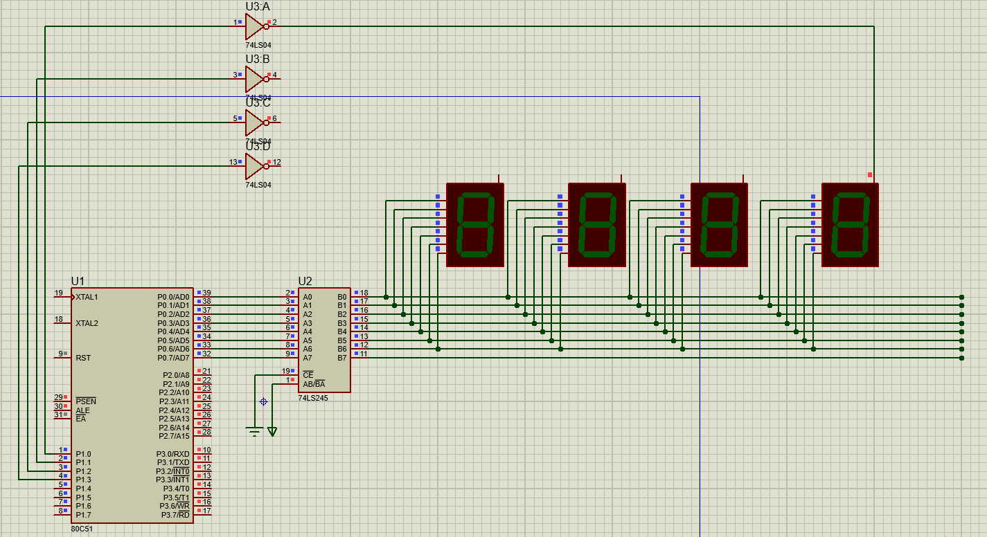
结果加上反向器数字 8 无法显示?
去掉!
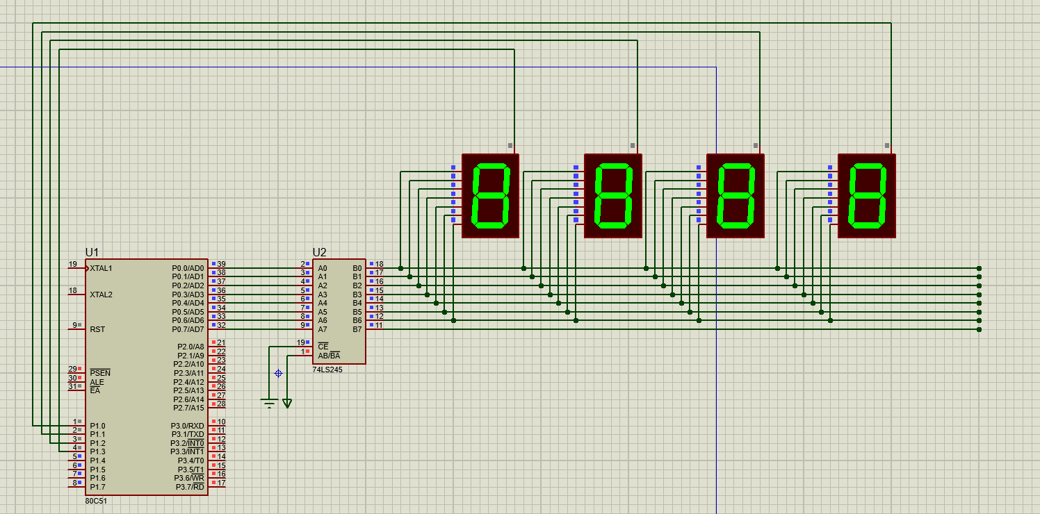
NICE!
/* Main.c file generated by New Project wizard
 *
 * Created:   周四 2月 28 2019
 * Processor: 80C51
 * Compiler:  Keil for 8051
 */

#include <reg51.h>
typedef unsigned char      uint8_t;
// 0~9 数字字模
const uint8_t n[10] = {0x40, 0x79, 0x24, 0x30, 0x19, 0x12, 0x02, 0x78, 0x00, 0x10};

void main(void)
 {
    // Write your code here
    int num[4];
    int nums = 2019;
    int sleep = 100;
    uint8_t i;
    uint8_t tube_select;
    for(i = 3; i >= 0; i--)
    {
      num[i] = nums % 10;
      nums  /= 10;
    }
    while (1)
    {
        tube_select = 0x01;
        for(i = 0; i < 4; i++)
        {
            P0 = n[num[i]];
            while(sleep--);//模拟软件不加延时看不出效果!
            P1 = tube_select;
            tube_select <<= 1;
        }
    }
 }